
INTRODUCTION:
Phase Two improvements to the John D O’Bryant School of Math & Science involved construction of a new main entryway along Malcolm X Boulevard, as well as a new stair tower and access ramp at the rear of the building.
Geotechnical Conditions:
Soil conditions explored by project geotechnical engineer, Haley & Aldrich, Inc. consisted of 9 feet of clay FILL over stiff marine CLAY followed by bedrock at about 20 feet. Groundwater was encountered at 12 feet below grade.
Project Challenges:
Economically supporting the heavily-loaded stair tower addition to the existing building proposed over urban fill.
Advantages
- Cost savings over traditional deep foundations
- Flexibility of installation from various grades and locations
- High capacity for reduction of scope
- Rapid installation
Design and Construction Solution:
The heavy loads associated with the new stair tower addition for the three-story building required a support solution beyond conventional spread footings because of the urban fill. The geotechnical engineer ruled out overexcavation and replacement of the fill because of excavation depths and access issues. Small-diameter (9-inch) drilled micropiles with capacities of 20 tons were recommended and included on the structural plans. The micropiles were specified to terminate in the stiff marine clay with lengths of 20 feet.
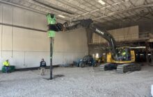
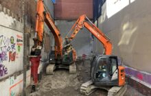
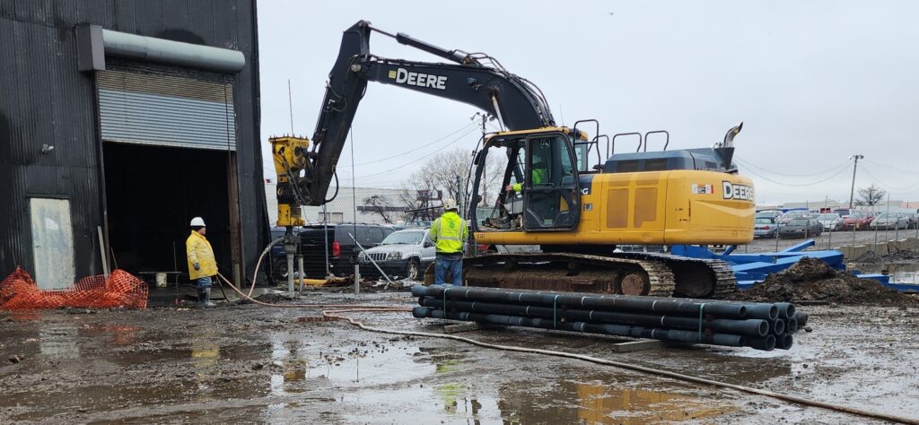
While Helical Drilling proposed on the base micropile scope of work, they also worked with the general contractor and geotechnical engineer to develop a cost-saving alternative consisting of Ductile Iron Piles (DIPs) to reduce the foundation support costs by more than half. A one-for-one replacement with the proposed micropile design was used for expediency despite having allowable DIP capacities of 75 kips (Series 118/7.5). The DIPs were designed with lengths of 15 feet. Installations terminated in the clay or at the top of rock with lengths ranging from 15 to 27 feet. The ease of adding 5 meter long DIP sections allowed for little issue with the variation in lengths from the plan.
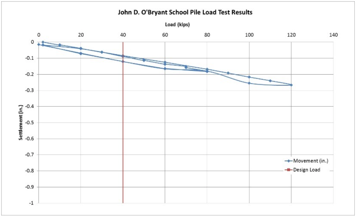
Load testing of the end-bearing Ductile Iron Piles showed a deflection of about 0.1 inch at the design load (100%) of 40 kips. The load tests were performed to 300% of the design load (120 kips). The response was nearly perfectly elastic with a deflection at the maximum test load of slightly less than 0.3 inches.
Project Team Members
DIP Design/Build Partner: Helical Drilling, Inc.
Geotechnical Engineer: Haley & Aldrich, Inc.
General Contractor: Colantonio, Inc.
Structural Engineer: Souza, True and Partners
Architect: Miller Dyer Spears