
Installation & Equipment
How DIPs Are Implemented
Ductile Iron Piles are installed using an excavator-mounted hydraulic hammer fitted with a special drive adapter that drives the pile into the ground using a combination of the percussive energy from the hammer and the excavator crowd force. Two main types of installation methods exist for the Ductile Iron Piles: Non-grouted (dry) DIPs and exterior grouted DIPs. While the same Ductile Iron Piles are used in each system, the installation process and accessories do vary depending on the method selected for installation.
Non-Grouted Piles
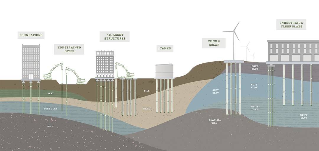
1) Ductile Iron Piles installed using a non-grouted or dry approach begin by first cutting the taper off the first pile section and inserting a flat or pointed driving shoe over the end of the hollow pile.
2) The 5 meter pile section is then positioned vertically (or at the appropriate batter angle if applicable) and driven into the ground using high-frequency impact energy delivered from a hydraulic hammer. The pile is driven until the belled Plug & Drive socket end is nearly at the working grade. The driving resistance (time required to drive each meter increment) is measured during driving.
3) A second DIP section is then lifted into place so that the tapered or spigot end of the second DIP section is inserted into the socket end of the existing pile.
4) The driving process is repeated.
5) This process continues until the pile terminates on refusal or achieves the required driving criteria (typically 1 inch in 50 seconds) or develops sufficient length to achieve the frictional capacity along the roughened Ductile Iron Pile surface.
6) When interior grout is being used, the grout is placed either after the pile achieves the required set or later in the process after multiple piles have been installed. Note that the reference to non-grouted pile refers to the use of the grout during the driving to fill the exterior annular space. It is almost always the case that non-grouted piles are grouted on the interior for added strength and corrosion resistance.
Exterior Grouted Ductile Iron Piles
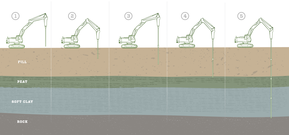
1) Ductile Iron Piles installed using an exterior grouted approach begin by first cutting the taper off the first pile section and then inserting a specially-designed patented conical grouting shoe over the end of the pile. The conical -grouting shoe is designed specifically for grouting applications and is larger in diameter than the outside pile diameter to create an oversized annular space around the pile that facilitates grout encapsulation around the exterior of the pile. The unique grouting method allows grout to be pumped directly to the base of the pile to ensure grout volume at the critical locations in the pile (compared with gravity fed pile systems that “pull-down” the grout in the pile with no way to verify the continuity of grout to the bond zone.
2) The pile is then driven into the ground using high-frequency impact energy delivered from the hydraulic hammer using a specially-designed grout driving shank that allows the simultaneous pumping of grout during driving. The grout flows from the concrete pump into the grout reservoir and shank and then down the interior of the pile. The grout fills the interior of the pile and travels out the grout ports in the conical grouting shoe and alongside the DIP. The grout is pumped to maintain a grout return while creating the grout/soil interface to provide efficient skin friction along the friction DIP.
3) The pile is driven and grout is pumped continuously until the Plug & Drive socket end is nearly at the working grade. The driving resistance (time required to drive each meter increment) is observed during driving.
4) A second DIP section is then lifted into place so that the tapered or spigot end of the second DIP section is inserted into the socket end of the existing pile.
5) The driving / grouting process is repeated.
6) This process continues until the pile extends to a sufficient design depth in the competent bearing layer (bond zone) to develop the required frictional capacity through grout-to-ground bonding or encounters an end-bearing layer.
7) In the event that tension resistance is also required, a high-strength center bar is inserted into the wet grout to engage the frictional capacity and provide high tension resistance.
Installation Equipment
One attractive feature of the Ductile Iron Pile system is that it uses conventional earthwork equipment for installation including a single medium-duty excavator, hydraulic hammer and grout pump. The amount of specialized equipment and tooling is limited to the drive tools.
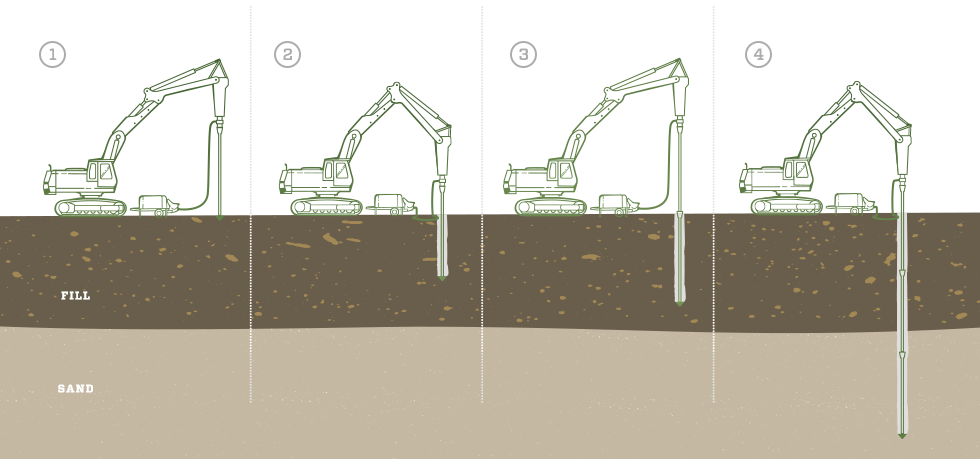
1) Base Excavator Machines
Base crawler excavators used for Ductile Iron Piles are typically in the 18 to 30 ton service or operating weight range. Alternatively, vertical-mast equipment with a hydraulic hammer may also be used for installations. The two primary factors for base excavator selection are the need to a) have sufficient height of the hammer to reach on top of the pile for driving and b) supply the required hydraulic power to the hammer. Therefore, compatibility of the base excavator with the hydraulic hammer is extremely important to both equipment performance and pile installation.
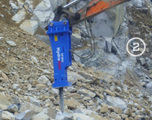
2) Hydraulic Hammer
The hydraulic hammer is a critical part of the Ductile Iron Pile installation process. Selection of the hammer is equally as critical to ensure 1) adequate hammer energy to drive the piles to obtain proper “set” conditions and 2) avoid overstressing and damaging the pile during driving. Factors that should be considered when selecting an appropriate hammer for DIP installation include:
- Pile diameter (98 mm, 118 mm or 170 mm)
- Grout cap diameter (if applicable) – (150 mm to 370 mm)
- Pile length
- Soil conditions (loose, dense, debris fill, etc)
- Pile design capacity
- Pile type:
- Friction
- End-bearing with “set” criteria
- End-bearing on refusal
It is important that the hammer flow requirements are properly matched with the base excavator for adequate functionality. In addition, connection of the hammer to the excavator will depend on the specifics of each piece of equipment. Specialty adaptors may be required to make the proper hammer-excavator connection and need to be investigated by the installer. Many installers elect to use side-mount hammer brackets to reduce the amount of overhead clearance needed for the system installation which also reduces the excavator size requirements.
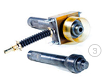
3) Drive Shanks
Specialty drive shanks are required for installation of the Ductile Iron Piles. A solid (dry) drive shank is used for non-grouted pile installations and a grouting (wet) shank along with a grout box is used for exterior grouted pile installations. It is recommended that the wet shank primarily be used for exterior grouted pile installations and not for repeated end-bearing situations to avoid tooling damage. This damage potentially is largely because the combination of the high energy imparted during the driving process combined with the heating of the tooling that can occur without the presence of grout to act as a coolant during installation.
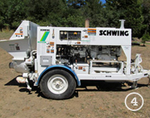
4) Grout Pump
A grout pump is required for installation of exterior grouted Ductile Iron Piles also for filling of the interior of the pile following installation of Non-Grouted piles. A colloidal pump is typically used for mixing neat cement (cement and water) for filling the interior of piles. A piston-driven, swing-tube concrete/grout pump is recommended for pumping sand-cement grout during the installation of Grouted DIPs. Although screw pumps can deliver high rates of delivery, they are not suitable for ductile iron pile installations because of the limited discharge pressure generated.
Like hammer selection, it is important that the grout pump be selected so that it is large enough to provide sufficient pumping pressures to introduce the grout at depth in the pile, but is not too large that it causes blockages in the line or over-pressurizes the system. Manufacturer recommendations indicate a maximum pumping pressure up to 1,000 psi (70 bars) and with a flow rate of 12 cfm (20 m3/h). The pump stroke size is also critical to avoid plugging. Pump strokes of ¼- to ½-cubic foot per stroke are well-suited for DIP installation.
During grouted DIP installation, the grout pump lines are connected to the grout box attached to the grouting (wet) shank in the hammer. Since the connection to the wet shank is a 2 inch (50 mm) connection, hose reducers are often required from the 4 inch (100 mm) or 6 inch (150 mm) line extending from the pump.