INTRODUCTION:
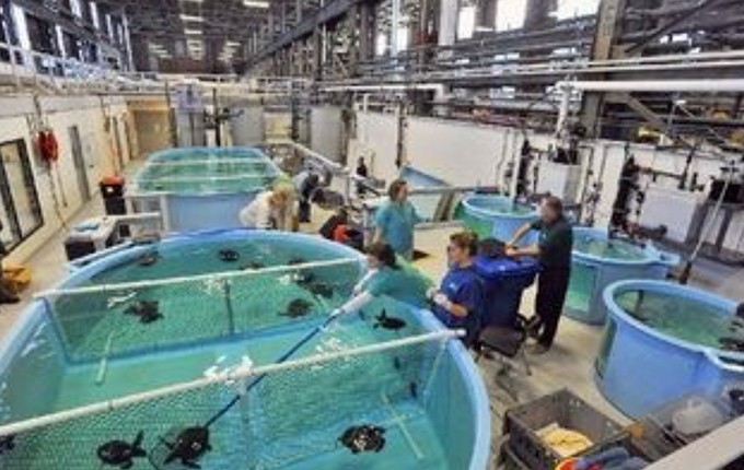
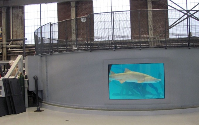
Plans for conversion of an existing shipyard manufacturing building to the New England Aquarium Temporary Marine Holding Facility for injured sea mammals included the construction of new temporary holding tanks for marine creatures with diameters up to 33 feet and heights of 10 to 12 feet and CMU block walls. The single-story facility with a 33-ft tall bay height was constructed in 1940 on a combination of spread footings and pile foundations. The interior slab-on-grade floor system had experienced considerable settlement and cracking over the years and was inadequate for supporting the improvements. Designs were prepared for a new 48-ft by 120-ft pile-supported structural slab system for the improvements.
Geotechnical Conditions:
Soil conditions in the area of the new holding tanks consisted of up to 16 feet of sand and gravel fill with ash, clay, timber and other deleterious materials. In one end of the site, the fill was underlain by up to 8 feet of soft to stiff organic silt followed very stiff to stiff marine clay. In the other end, the fill was underlain by medium dense sand followed by bedrock. Groundwater was encountered at 8 feet below grade.
Project Challenges:
Provide a structural support solution for the new holding tank slab to bypass the fill and organic soils while working within the interior of the existing facility.
Advantages
- Cost savings over traditional deep foundations
- Flexibility of installation from various grades and locations
- High capacity for reduction of scope
- Rapid installation
Design and Construction Solution:
Initial considerations were given to helical anchors for structural slab support. Helical Drilling, Inc. worked with the project geotechnical/structural engineer to consider Ductile Iron Piles as an alternative to deliver higher capacities and reduced cost. Design documents were prepared for either helical anchors or DIPs. The general contractor selected the DIP option provided by Helical Drilling, Inc. to support the 9-inch thick structural slab with 9-inch haunches at pile locations.
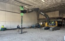
Several DIP types were considered because of the variable geotechnical conditions. Final plans incorporated a 60 kip capacity end-bearing DIP in areas with very stiff clay and a 40 kip capacity friction DIP terminating 15 feet deep into the sand layer in other areas. Although working within an existing building, the available headroom allowed for use of a CAT 320 excavator with a Tramac 900 high-frequency vibrating hammer to install the 78 DIPs.
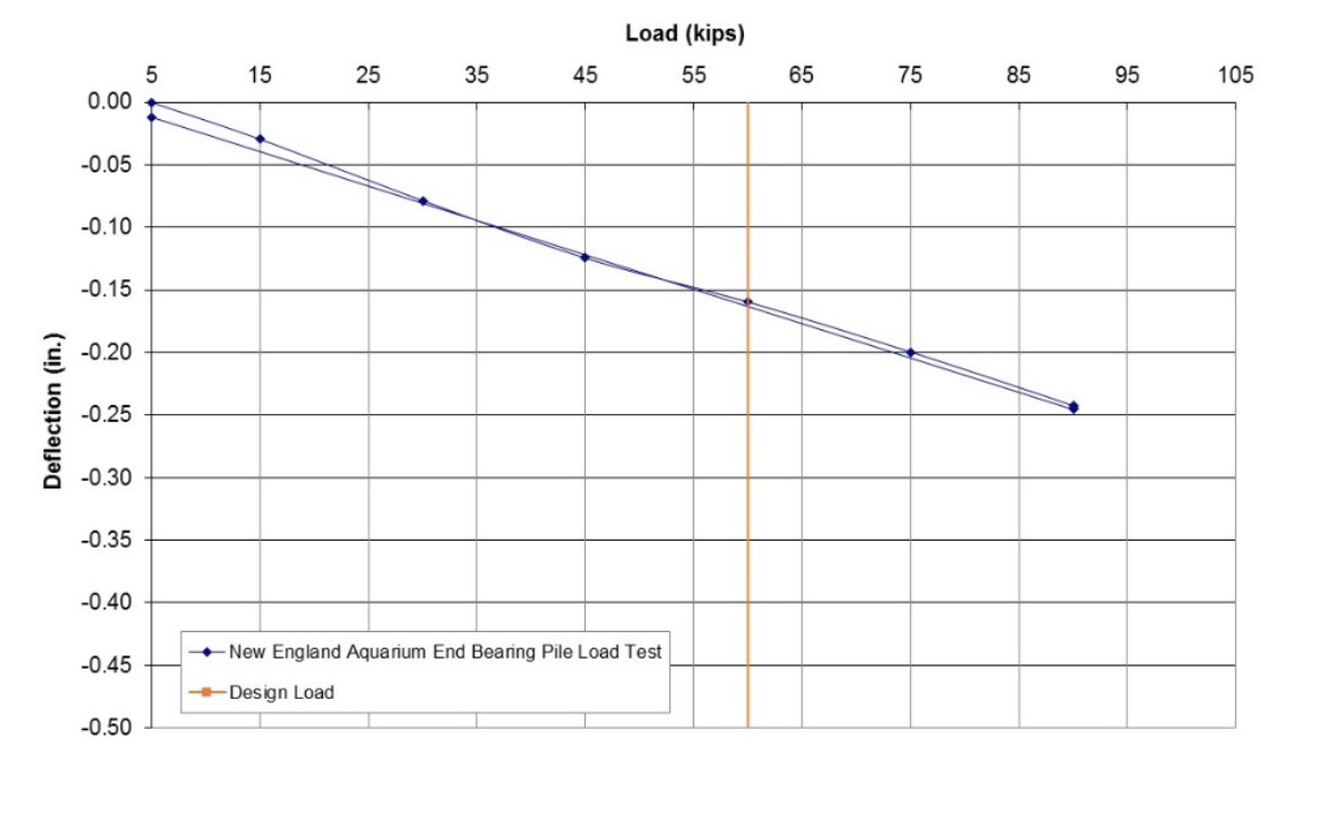
End-Bearing
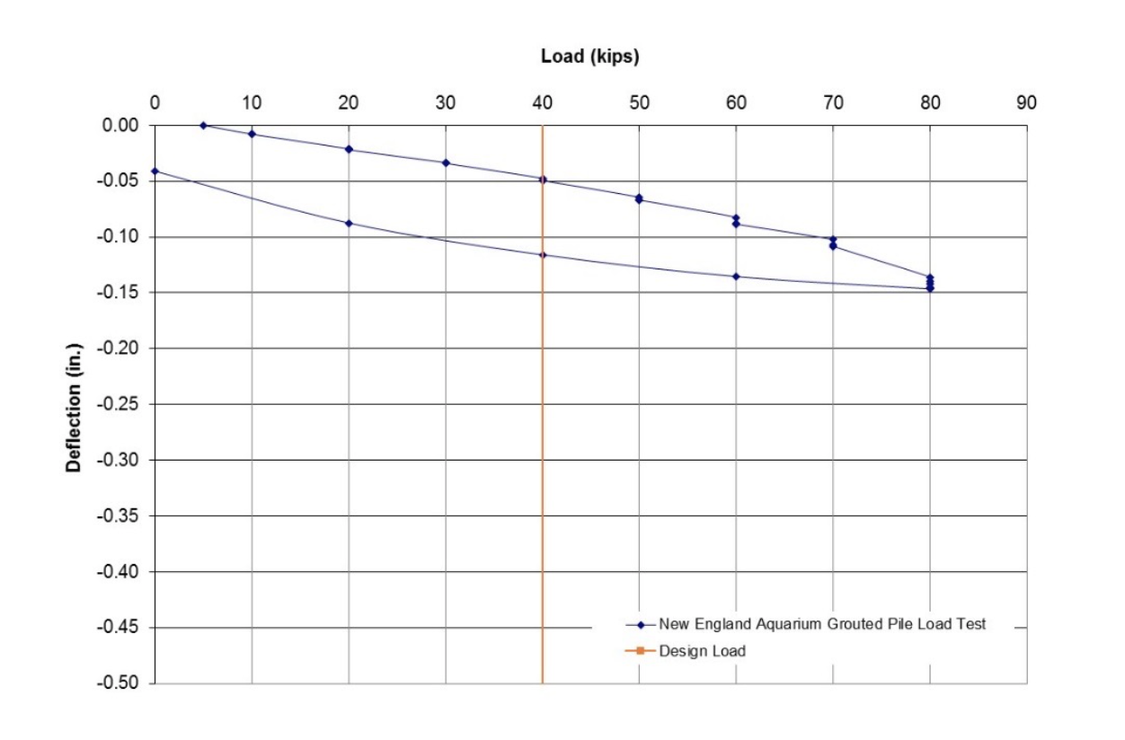
Friction
Load tests on both friction and end-bearing Ductile Iron Piles were performed. The friction piles were driven to a depth of 30 feet to provide proper friction embedment. The end-bearing piles were driven to a depth of 62 feet and a refusal criteria of less than 1 inch of penetration while advancing the pile for the last minute. Results of the load tests for both pile types showed less than 0.2 inches of movement at the design loads and nearly elastic performance to loads of 80 kips or higher.
Project Team Members
DIP Design/Build Partner: Helical Drilling, Inc.
Geotechnical Engineer: Weidlinger Associates, Inc.
General Contractor: Turner Construction
Structural Engineer: Weidlinger Associates, Inc.
Architect: McManus Architects, Inc.

