Introduction:
Construction of the West Harbour GO Station in Hamilton, Ontario is part of the Metrolinx regional transportation plan that features train and bus service along with the Lakeshore West Line. The station is an integral part of the proposed Hamilton Light Rail Transit enabling connection to the John C. Munro Hamilton International Airport. The station development involved construction of a concrete segmental retaining wall running west from the Bay Street Bridge Abutment.
Geotechnical Conditions:
Soil conditions consisted of up to 4.6 m of sandy silt / silty sand fill underlain by loose to compact silty sand / sandy silt extending to depths of up to 12 m. Soft to very stiff clayey silt and silty clay extended to depths up to 22 m followed by glacial till (clayey silt / silty clay) extending up to 30 m. Rock was encountered below the glacial till. Groundwater was encountered at 2.4 to 4.6 meters below grade.
Project Challenge:
Construct the new retaining wall over soft, compressible clay at a limited-access site where vibration and impact on adjacent active railroad and site works had to be minimized.
Advantages
- Rapid Ductile Iron Pile installation
- Limited vibrations immediately adjacent to existing rail lines
- Modular Ductile Iron Pile system reduced issues with laydown areas and driving access
- Work from variable grades reduced site preparations and logistics issues
Design and Construction Solution:
The design team initially considered various foundation support options for the new 43 meter long
retaining wall with heights up to 5 meters. Shallow foundations were quickly eliminated because of
the soft nature of the site soils and settlement concerns. A driven H-pile solution was initially selected
and designed for 40 piles with a structural capacity (ULS) of 1,300 kN. However, the H-pile option was
challenged with practical construction issues including excessive vibrations, extended working pad and
laydown area requirements, access issues requiring excessive splicing of battered piles and variations
in working grades causing challenges for installation equipment and inefficient pile material usage.
Working closely with the design team, a Ductile Iron Pile alternative was proposed for support of the
retaining wall. The Ductile Iron Pile solution consisted of 74 piles with a structural capacity (ULS) of 725
kN. The pile design included a 118/7.5 Ductile Iron Pile section (118 mm outside diameter with 7.5 mm
wall thickness) along with a #8 reinforcing bar centered in the pile and 20 MPa grout. The piles were
installed to depths ranging from 25 m to 28 m to bear on rock. Design at the site was verified with a
full scale load test performed to 1,036 kN. Maximum (gross) deflection at the maximum test load was
limited to 18 mm with much of the deflection occurring as a result of elastic shortening of the pile.
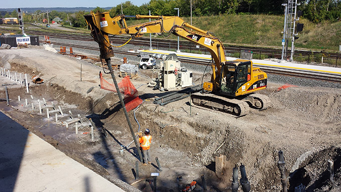
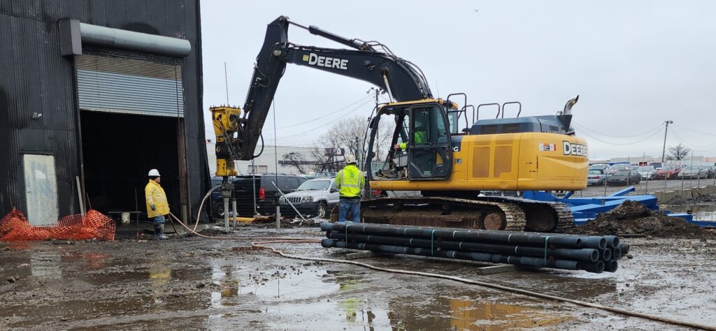
GeoSolv Design/Build Inc. installed a total of 39 vertical and 35 battered (3:1) piles in 12 shortened
working days Installations using a medium-sized CAT 315 excavator allowed the crews to work from
variable grades without the need for significant working grade modifications. The modular Ductile Iron
Pile sections allowed for battered pile installation without obstruction due to existing adjacent retaining
walls. The limited vibration generated with the system reduced potential issues with slope stability or
impact on nearby rail activity.
Project Team Members
DIP Design/Build Partner: GeoSolv Design/Build
Geotechnical Engineer: exp Services, Inc.
General Contractor: Kenaidan Contracting Ltd.
Structural Engineer: IBI Group
Architect: IBI Group

