Ductile Iron Piles – not getting pushed around….
When you need a deep foundation system to resist lateral forces, small diameter piles might not be the first thing you think about. Yet, many limited access or low overhead clearance projects utilizing low vibration Ductile Iron Piles still require some degree of lateral load resistance. You might expect that the lateral capacities of small diameter DIPs are on the lower side. So…it’s a fair question – “How much lateral capacity can Ductile Iron Piles provide?”
Lateral capacity of any pile system is related to both the structural bending capacity of the element as well as the interaction between the pile and surrounding soil. Capacities are also impacted by the amount of axial (normal) load applied to the pile and whether it’s an individual pile or group of piles. The lateral load vs. deflection behavior of Ductile Iron Piles is analyzed similar to other pile systems. Computer programs like ENSOFT Inc.’s LPile or GROUP, Deep Excavation’s DeepFND or Civiltech’s AllPile are used to easily analyze the pile interaction with the surrounding soil.
Despite the modular nature of the system, extensive research has shown that the innovative Plug & Drive (bell-spigot) joint forms a full moment-resisting connection attributed to the significantly increased pile section at the joint combined with the hoop stresses and cold-welding generated during driving the tapered end into the socket. Lateral testing on piles with joints at various depths below grade has repeatedly shown that the joint depth has no effect on lateral capacity, further confirming the integrity of the moment-resisting joint. The DIPs can simply be modeled with the straight-line pipe section as the controlling section.
Allowable lateral capacities for dry installation (no exterior grout) often range from a few kips for the smaller pile sizes up to 10 kips or more for larger pile sizes. For design, axial capacities must also consider a combined bending analysis to avoid overstressing the pile section. If improved lateral capacity is needed, a number of alternative approaches are possible including:
- Using “converters” to transition from a small diameter pipe to a larger diameter pipe in the upper portion where bending stresses are the highest.
- Installing with oversized grout shoes to produce a larger diameter-grouted pile section for improved load-deflection behavior. Larger pile diameters can develop greater resistance to penetration into the surrounding soil, offering increased lateral capacity.
- Installing with an oversized, steel casing in the upper portions of the exterior grouted DIP to increase bending capacity.
- As an alternative to bending of a vertical pile, Ductile Iron Piles can also be installed on a batter to provide additional resistance for lateral loading.
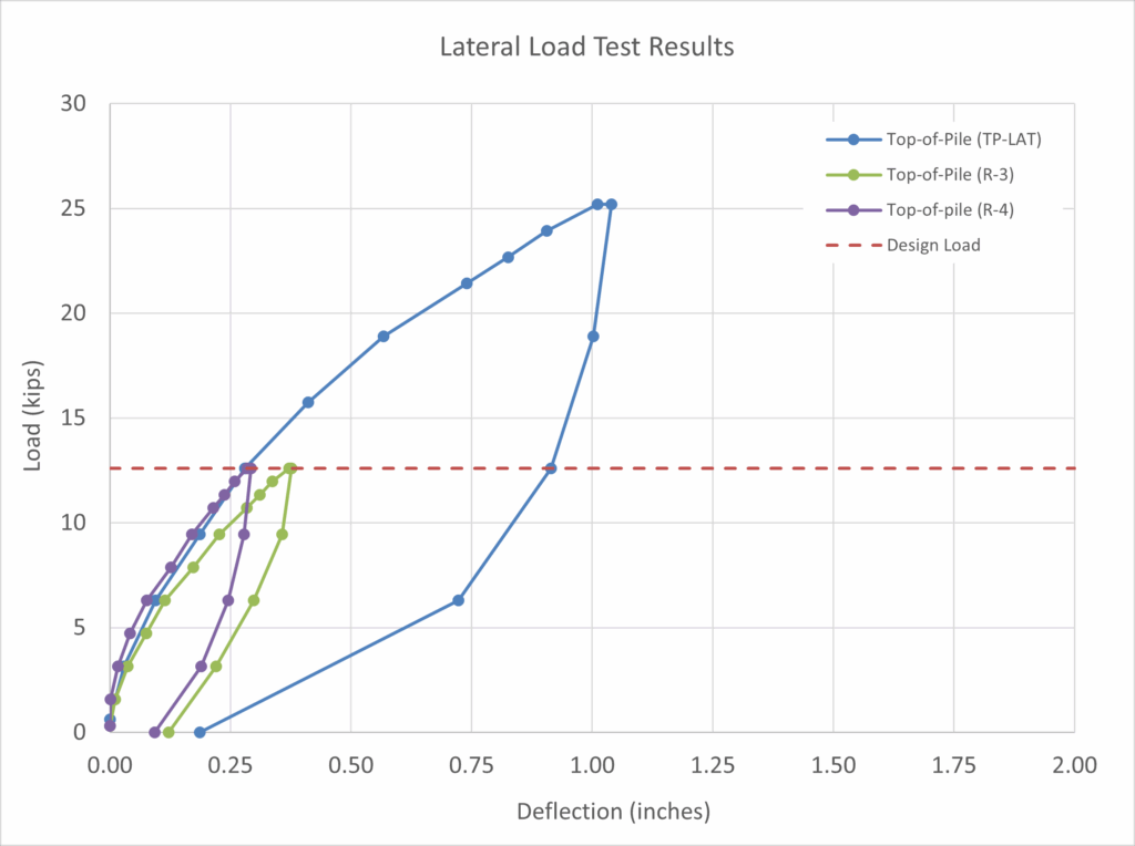
Results of recent lateral load testing on a Series 170/9.0 pile (170 mm O.D. with 9 mm wall thickness) tested in a free-head condition showed less than 0.3 inches of deflection at an applied load of 12.6 kips and about 1 inch of deflection at an applied load of 25 kips when installed on a site with a few feet of loose to medium dense fill underlain by very soft alluvial soils.
On another site with “urban” fill extending 20 feet below grade followed by stiff to very soft clay, testing was performed on an exterior grouted Series 118/9.0 installed with a 270 mm (10.6-in) grout shoe. A 12-ft section of 9.625-inch diameter, 0.472-inch-thick steel casing was wet-set into the exterior grout. Test results showed less than 0.5 inches of movement at loads of 48 kips.

While many of our projects require only a few kips of lateral resistance, solutions for higher lateral loads are feasible with DIPs. Have additional questions about lateral loading on Ductile Iron Piles? Please reach out to discuss with our engineers or refer to our Tech Brief on Bending and Lateral Resistance on our website. Interested in evaluating a Ductile Iron Pile option on your project? We’re pleased to prepare a project-specific feasibility assessment, preliminary design approach and material quote to evaluate the potential value offered by TRM’s Ductile Iron Piles. FAST. SIMPLE. SAFE.®
Although pile selection for the following projects wasn’t driven by purely lateral load resistance, these jobs utilized Ductile Iron Piles to resist both axial and lateral loads.
PROJECT EXPERIENCE – ARTEMAS APARTMENTS
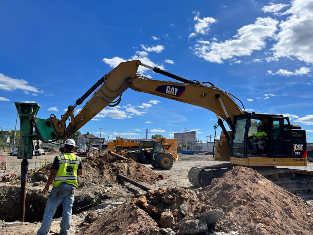
Construction of a new 112,000 sqft, 6-story building required a foundation solution along a portion of the building to limit vibrations and transfer loads below the zone of influence of adjacent utilities. The project geotechnical engineer recommended both drilled micropiles and Ductile Iron Piles (DIPs) to extend nearly 100 feet through fill, organics and thick marine clay to terminate in glacial till and/or on rock. The piles needed to provide resistance of 90 tons (compression), 10 kips (tension) and up to 10 kips (lateral). A Series 170/9.0 pile was designed to provide the required capacities. Offering cost savings of more than $500k and substantial schedule savings, the project team selected DIPs. Following a testing program to confirm the vibration levels and verify performance, the DIPs were approved as a safe solution to minimize risks to the adjacent utilities as well as meet the performance for the project. The project was completed with over 110 production piles installed to depths of 84 to 109 feet in only 16 working days. For more information, check out the project summary.
PROJECT EXPERIENCE – WEST HARBOUR GO STATION RETAINING WALL
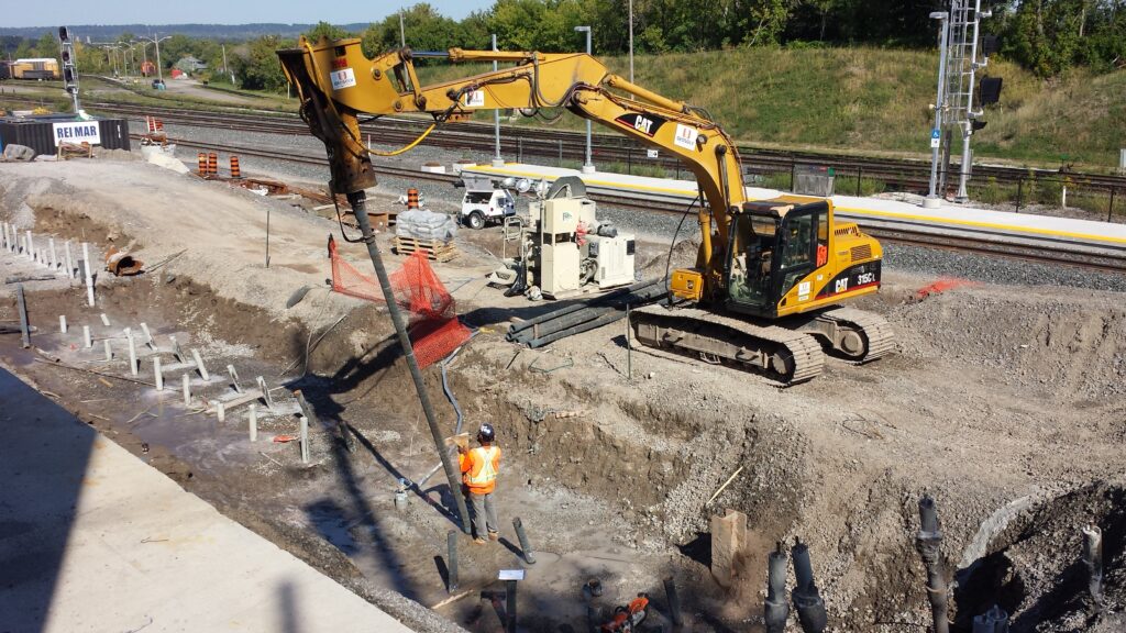
Construction of the West Harbour GO Station included a concrete segmental retaining wall running adjacent to an existing roadway abutment. Plans originally required the use of steel H-piles to penetrate 20 ft of fill followed by up to 35 feet of sand underlain by up to 70 ft of soft to stiff clay and terminate on glacial till / rock at depths up to 100 ft. However, retaining wall support required a combination of vertical and battered piles to provide resistance to both vertical and horizontal loads. The H-pile installation was logistically challenged due to excessive vibrations near the railroad tracks, extended working pad and laydown area requirements and access issues requiring excessive splicing of battered piles. A low vibration Ductile Iron Pile alternative was selected to efficiently install both vertical and battered piles at the site. The piles were successfully installed working from variable grades in close proximity to both the active railroad as well as the existing abutment. A load test performed to 233 kips confirmed the design load. A total of 74 piles were installed in only 12 shortened workdays helping avoid schedule delays associated with the H-piles. For more information, check out the project summary.