
Ductile Iron Piles – Common Structural Myths
Structural Myth 1: The Ductile Iron Pile Bell and Spigot (Plug & Drive) Connection creates a discontinuity or weak joint in the pile.
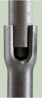 The innovative Plug & Drive connection provides a unique advantage for the rapid installation of the Ductile Iron Pile system. As shown in the figure, each pile section is manufactured with a thickened, reinforced bell section and a tapered (spigot) end section. The joint is engineered to accept the tapered pile end and develop a connection through two mechanisms: 1) significant hoop stresses (confinement) that develop as the tapered end is driven into the interior of the bell and 2) a friction (cold) weld that occurs during the high frequency driving process between the ductile iron bell-spigot interface.
The performance of the Plug & Drive connection has been heavily scrutinized and verified through a variety of different research efforts including numerical analyses, laboratory tests, and field tests. Researchers have evaluated the compressive capacity of the pile socket and concluded through numerical modeling and laboratory testing that the region around the pile socket does not constitute a weak point with respect to the load carrying capacity of the pile. The primary driver in the structural pile capacity is actually the straight-shaft section of the pile itself due to the smaller dimensions and cross-sectional area of pile material. The integrity of this joint is further strengthened with the addition of interior grouting which improves the stiffness.
 Field tension testing of the connection for purposes of isolating and evaluating the tensile performance of the pile socket cold-weld have been performed. Test loads of over 30 kips have been applied on a Series 118/7.5 pile without failure, suggesting that the integrity of the pile socket cold-weld remains intact under tension loads.
Additionally, GRL Engineers, Inc. recently performed pile dynamic analysis (PDA) testing on instrumented piles to verify the pile capacity. As part of the monitoring, engineers measured the dynamic response of the pile during the impacts from the high frequency percussion hammer. At the start of driving, readings were reflective of a discontinuous pile (similar in nature to a broken pile) due to the modular pile sections. As the percussive drive energy was applied to the pile, continued monitoring revealed continuous pile behavior after the Plug and Drive connection had fused (Ryberg 2021). This monitoring provided further confirmation of the cold-welding connection that is generated during installation.
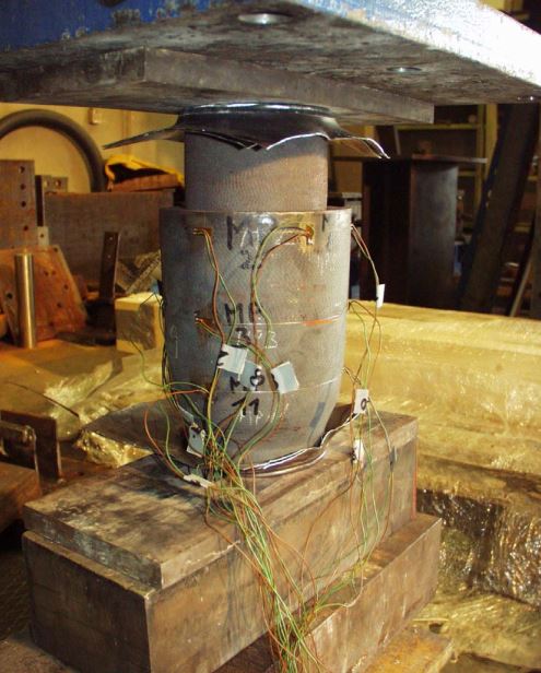
Lastly, bending testing has been performed to compare the bending resistance between the pile socket and the straight-shaft pile material. Three- and four-point bending tests were performed on a control section (straight shaft) as well as the pile socket (bell-spigot) and coupled sections for various pile sizes. The test results all followed similar behavior where the critical bending resistance is characterized by the straight shaft properties. From a design perspective, the pile bending behavior is modeled based on the straight shaft properties as the limiting factor, and knowing that bending performance of the bell-spigot joint will exceed the engineering properties of the straight shaft section.
For more details on the integrity of the Plug and Drive connection, please check out our Tech Brief.
Structural Myth 2: Ductile Iron Piles can’t be used to resist tension loads.
While the unique Plug-and-Drive (bell-spigot) connection forms a friction-welded joint that has been shown to resist considerable tension loads, Ductile Iron Piles rely on a more conservative and conventional design approach for tension resistance by utilizing a high-strength threaded center bar to carry 100% of the tension demand. After installing the pile to design depth, the center bar is wet-set within the cement grout inside the pile interior. Tension loads applied to the bar are then resisted through the mobilization of friction along the pile. Depending on the installation method, the frictional capacity is developed through the interface between the roughened pile surface and the soil for a non-grouted (exterior) pile, or via the pile’s perimeter grout-to-ground bond zone for exterior grouted piles.
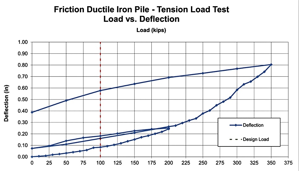
How much tension capacity can you actually achieve? That depends on several factors, including soil conditions, pile length, pile diameter, center bar capacity, and whether the pile is installed with exterior grout or not. In a recent tension test program, an exterior grouted Ductile Iron Pile installed with a 10.6-inch (270 mm) diameter grout shoe achieved 350 kips without failing the 32-ft long pile. The test was stopped at 350 kips to avoid overstressing the center bar! Interested in learning more about tensile resistance, check out our Tech Brief describing Tension Resistance.
Structural Myth 3: Ductile Iron Piles can’t be used to resist lateral loads.
When you need a deep foundation system to resist lateral forces, small diameter piles are not the first thing you might think about. Yet, many projects that would benefit from Ductile Iron Piles for axial support still require some degree of lateral load resistance.
Lateral capacity of any pile system is related to both the structural bending capacity of the element as well as the interaction between the pile, pile cap and surrounding soil. Capacities are also impacted by the amount of axial (normal) load applied to the pile. The lateral load vs. deflection behavior of Ductile Iron Piles is analyzed like other pile systems. Computer programs such as Ensoft’s LPile or Civiltech’s AllPile are used to expeditiously analyze the pile interaction with the surrounding soil.
Since the Ductile Iron Piles are small diameter, allowable lateral capacities often range from a couple of kips for the smaller pile sizes up to 8 or 10 kips for larger pile sizes. For improved load-deflection behavior and added capacity, piles are often installed with oversized grout shoes to produce a larger exterior-grouted pile section to develop greater resistance to penetration into the surrounding soil and increased lateral capacity. As with most pile systems, lateral loads can also be resisted by installing the piles on a batter. Design considerations must also be given to the combined bending evaluation factoring in the axial loading demands.
Results of recent lateral load testing on a Series 170/9.0 pile (170 mm [6.69”] O.D. with 9 mm [0.35”] wall thickness) tested in a free-head condition showed less than 0.3 inches of deflection at an applied load of 12.6 kips and about 1 inch of deflection at an applied load of 25 kips when installed on a site with a few feet of loose to medium dense fill underlain by very soft alluvial soils.
Structural Myth 4: The Ductile Iron Pile system is too new and untested without enough project experience.
DuroTerra has been working with contractors and engineers on hundreds of projects across the United States and Canada benefiting from Ductile Iron Piles for almost a decade now. During this time, we have developed a track record for successful projects with significant load testing experience to verify and document the performance of Ductile Iron Piles in a variety of different conditions. Beyond our work in the United States and Canada, you might be surprised to learn that our manufacturer (Tiroler Rohre, GmbH) has more than 40 years of experience working with customers to support projects across 5 continents. While we continue to expand the geographic footprint with new geotechnical contractors and designers, the system has a track record of success that far exceeds expectations.

CONTACT US TODAY: info@duroterra.com / 781.817.6053