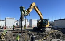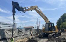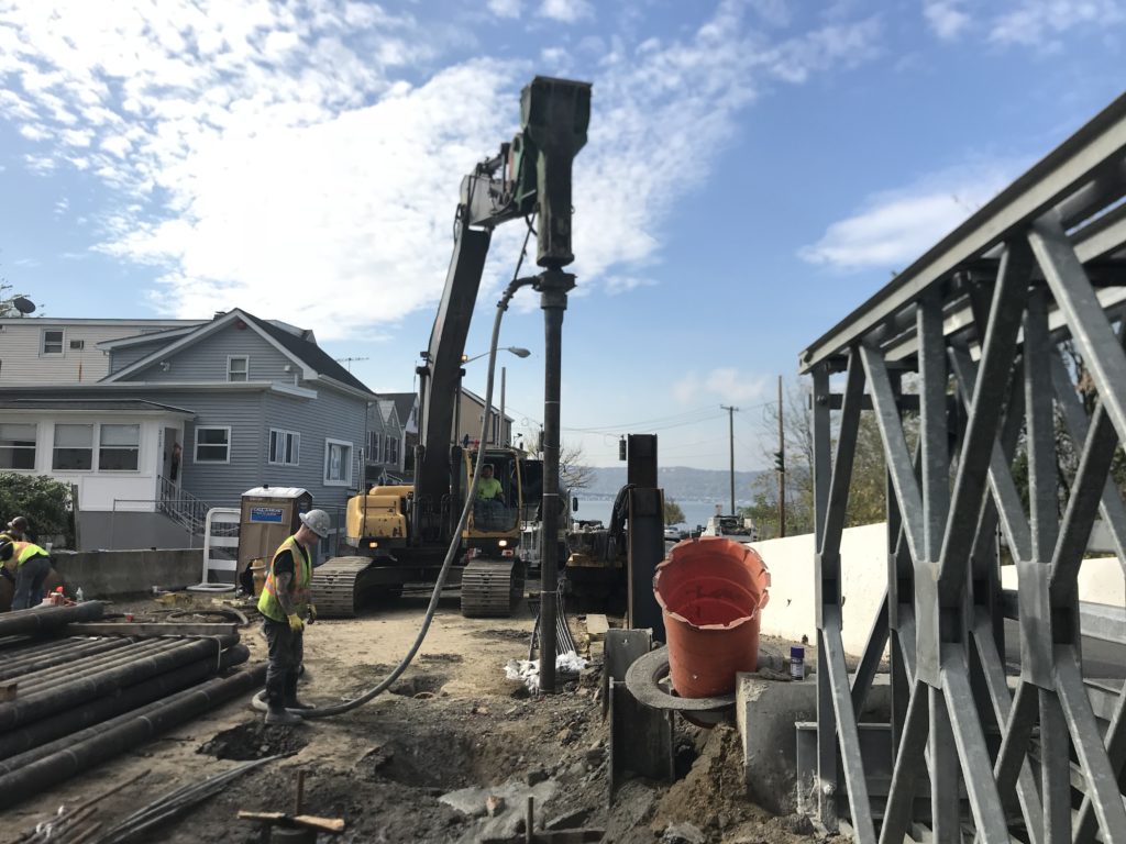
Ductile Iron Piles provide a low vibration deep foundation system for abutment support while working within a constrained and depressed work area
Project Description:
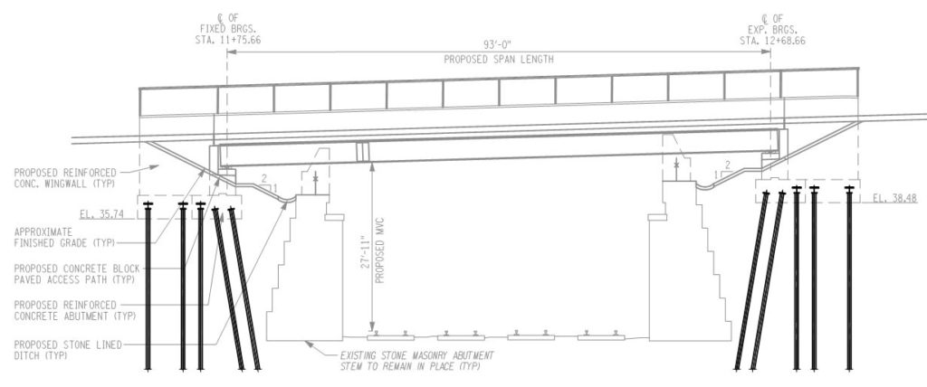
Construction of a new 93-foot long, two-lane, single-span bridge over the Metro North Railroad (Hudson Line) leading to the massive Edge-on-Hudson development on the Hudson River. Work involved construction of deep foundations for new bridge abutments positioned behind the existing abutments for the original bridge.
Geotechnical Conditions:
Soil conditions consisted of urban fill behind the original abutment extending 25 to 40 feet below grade followed by medium dense to dense sand to depths of 55 to 70 feet followed by stiff to hard silt and clay. The silt and clay extended to depths of 94 to 110 feet where decomposed rock was encountered. Groundwater was measured at 4 to 9 feet below grade.
Project Challenges:
Provide a low vibration deep foundation system for abutment support while working within a constrained and depressed work area behind the existing abutments. The project required substantial logistical and phasing coordination to complete work on both sides of the bridge while maintaining at least one lane of active traffic. With minimal staging area available, a clean and modular system was needed to minimize requirements for material laydown or spoils management (i.e. frac tanks).
Advantages
- Rapid installation compared to micropiles
- Clean process with no spoils generation
- Low displacement and low vibrations
- Develop capacity in end-bearing or friction
Design and Construction Solution
Foundation support for the new bridge abutments was originally designed on 9-5/8” diameter drilled micropiles with 100-ton allowable compression capacity and 30 ton allowable tension capacity (back row of piles only). In an effort to avoid applying stress to the existing aging abutment, the 92 micropiles were designed to be permanently cased through the fill to develop a free stress zone (upper 20 to 25 feet) and then extend a minimum of 50 feet below to develop capacity through bonding in the sand and silt/clay soils. Additionally, the front two rows of piles closest to the abutment face (and railroad) were designed with a 1H:6V batter to resist lateral loads.
A Ductile Iron Pile (DIP) value engineering alternative was proposed by Helical Drilling, Inc. to replace the micropiles on a 1:1 basis. The Ductile Iron Piles offered the advantages of faster installation speed, reduced cost and a cleaner installation process compared with the micropiles. The driven DIP option is a low vibration pile and would not cause concern for active railroad operations or nearby buildings. The DIP solution was conditionally selected by the design team and owner pending the performance of a successful load testing program.
A solution was developed consisting of Series 170/9.0 Ductile Iron Piles with a 1-1/4” Grade 150 center bar installed to develop end-bearing resistance on rock for the battered piles combined with Series 170/9.0 DIPs with the 1-1/4” center bar installed with a 270 mm grouting cap to achieve a 10-inch diameter grouted friction pile for both compression and tension resistance. The grouted piles were designed with bond lengths of 50-ft for an overall length of about 72 feet to match the micropiles.
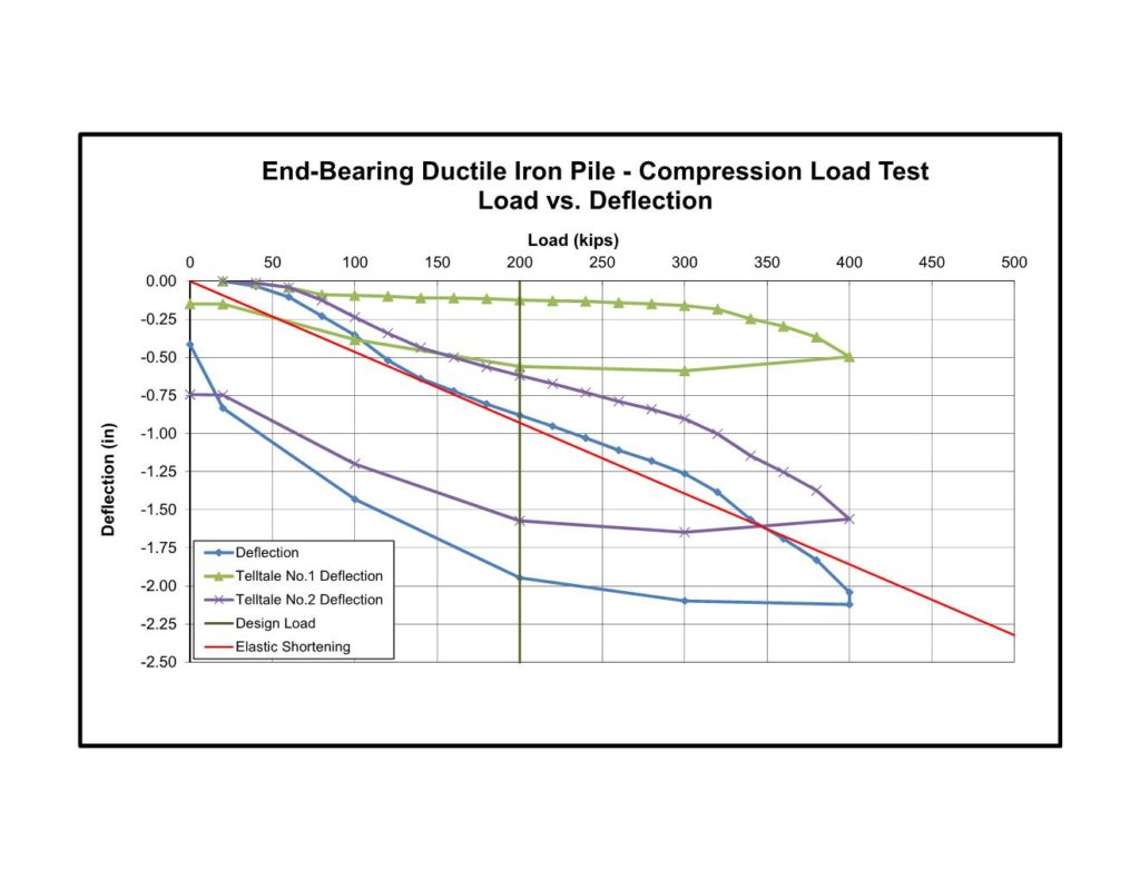
Helical Drilling developed a test program consisting of 3 full-scale load tests. One of the compression tests consisted of an end-bearing pile installed to a depth of 125 ft before achieving set of 50 seconds/inch on rock. The test pile was instrumented with telltales and strain gauges. Testing results showed 0.88 inches of deflection at 200 kips (100%) and 2.04 inches of deflection at 400 kips (200%) for the end-bearing pile. After unloading, with only 0.42 inches of total net deflection, the pile was reloaded up to 460 kips to illustrate a factor of safety of 2.3. Results of strain gauge measurements indicated that approximately 50% of the load was carried in skin friction along the 125-ft long shaft and the remainder was in end-bearing to the rock layer.
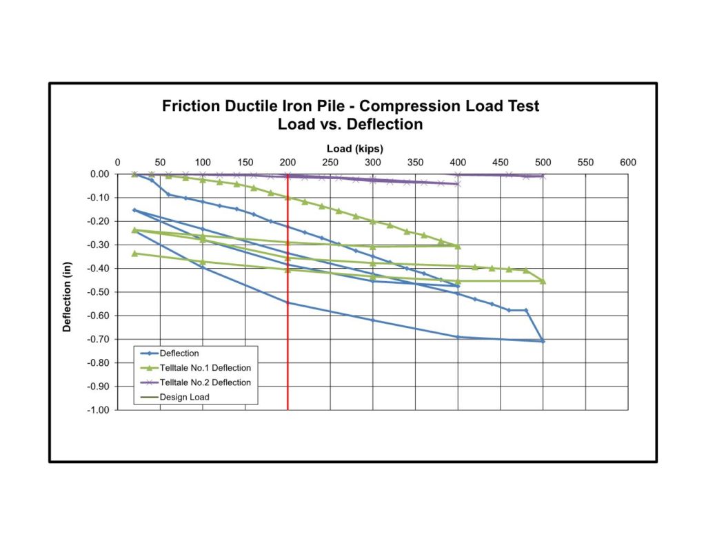
The second and third test piles consisted of grouted friction piles installed to 72 feet. Both piles were instrumented with telltales and the compression pile also contained strain gauges. Test results on the grouted compression pile showed even better performance than the end-bearing pile with 0.22 inches of deflection at 200 kips (100%) and 0.48 inches of deflection at 400 kips (200%). After unloading, with only 0.15 inches of total net deflection, the pile was reloaded up to 500 kips to illustrate a factor of safety of 2.5. Strain gauge measurements showed less than 10% of the test load reaching the bottom of the pile. The final full-scale test consisted of a tension load test performed on the grouted pile. Results showed only 0.32 inches of deflection at 150 kips (250% design tension load).
The first phase of work on the southern lane of the bridge was performed in winter conditions. A total of 46 piles (23 on each side) were installed to lengths ranging from 95 to 122 feet for the end-bearing piles and about 74 feet for grouted piles. After a lengthy delay for the construction of the southern portion of the bridge, the northern half was prepped and ready for the second phase of installation. Installation on the northern lane encountered similar conditions but driving lengths for end-bearing piles were slightly shallower to achieve “set” with piles ranging from 80 to 111 feet. In addition to the planned piles, a number of piles were installed to replace piles abandoned due to refusal when encountering buried obstructions from the original abutment foundation.
Project Team Members
DIP Design/Build Installer: Helical Drilling, Inc.
Geotechnical Engineer: Langan
General Contractor: Arben Group, LLC