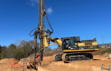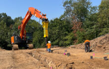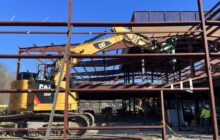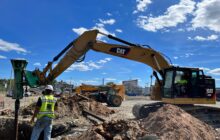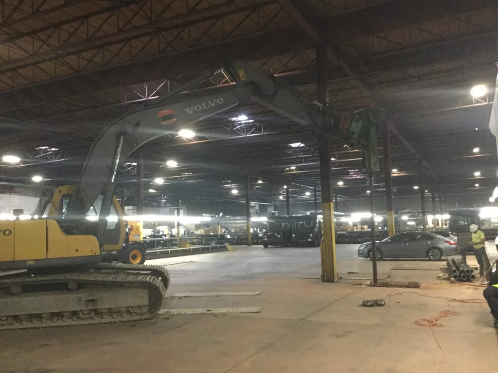
Ductile Iron Piles provided cost-effective and rapid foundation support for new interior columns while working around active distribution activities.
Project Description:
The project involved construction of a new mezzanine expansion within an existing shipping distribution facility. Overhead clearances ranged from only 20 to 30 feet. The addition of 34 new column locations required sawcutting of existing slabs prior to foundation construction. Column loads were up to 400 kips (compression) and 40 kips (tension).
Geotechnical Conditions:
Soil conditions consisted of up to 6 feet of clay fill underlain by very stiff to hard clay to depths of 7 to 13 feet below grade. Highly-weathered rock was encountered below the clay and extended to the maximum explored depths of 25 feet. SPT N-values in the weathered rock ranged from 53 bpf to 100 blows per inch.
Project Challenges:
Provide cost-effective and rapid foundation support for new interior columns while working around active distribution activities.
Advantages
- Rapid Installations compared with micropiles
- Substantial cost-savings compared with micropiles
- Low-overhead clearance for interior construction
- Low vibrations
Design and Construction Solution
Pile capacities of 40 tons in both compression and tension were specified for foundation support. Drilled micropiles consisting of 7 5/8-inch diameter piles socketed into rock to develop suitable bond capacity were selected to address the combined loading demands. However, during initial micropile installations, the micropile contractor did not encounter competent rock until depths of more than 40 feet below grade. In an effort to avoid substantial micropile change orders associated with the greater pile lengths, the design team determined that a reduced tension demand of only 5 tons was needed. This reduction allowed the use of short Ductile Iron Piles installed to set in the weathered rock to generate the 40 ton compression and 5 ton tension demands.
Helical Drilling, Inc. used Series 118/9.0 (118 mm outer diameter with 9 mm wall thickness) Ductile Iron Piles driven from the top-of-slab elevation to achieve set in the weathered rock. For piles requiring only 5 kips of uplift, a full-length #8 Grade 75 centerbar was centered in the grouted pile. For piles requiring up to 10 kips of working tension demands, an oversized 220 mm conical cap was used as a driving shoe. Cement grout was continuously pumped to encapsulate the pile during driving to create an effective 8.5-inch diameter grouted bond zone for greater uplift resistance. All piles were terminated by achieving a “set” of less than 1 inch in movement in 50 seconds or more with many of them refusing at less than ½-inch.
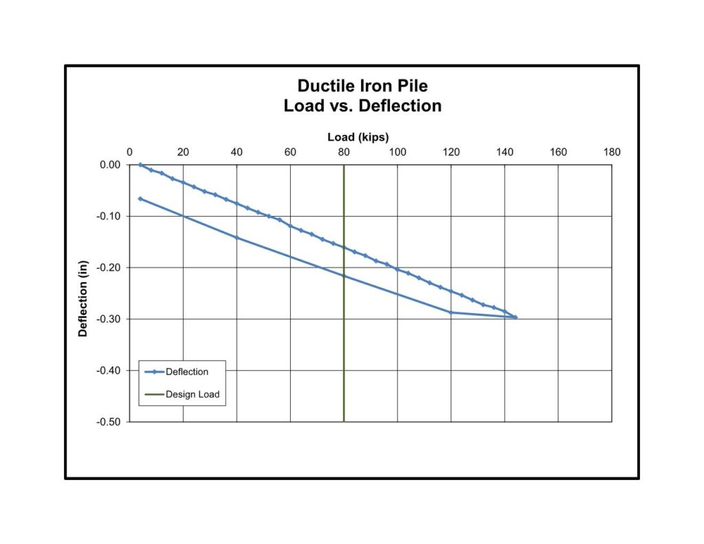
Full-scale load testing was performed on non-production piles. The compression test showed only 0.16 inches of movement at 40 tons (100%). At 72 tons (180%) and a deflection of 0.30 inches, the previously installed micropile reactions started to move and created an unsafe reaction condition and the test was discontinued. Results of the test were sufficient to confirm acceptable performance and met the design requirement. Tension testing performed on the pile installed with only a flat cap (no exterior grout) showed virtually no movement at the low load of 10 kips.
A total of 118 piles with average lengths of about 16 feet were installed in only 6 days. The crew worked within limited facility hours and navigated between excavated foundation areas. The use of the DIPs provided an undisclosed amount of cost-savings and reduced the schedule by more than a month compared with the original micropile approach.
Project Team Members
DIP Design/Build Partner: Helical Drilling, Inc.
Geotechnical Engineer: Geo-Technology Associates, Inc.
General Contractor: CVMNEXT Construction
Structural Engineer: CVM Engineers

