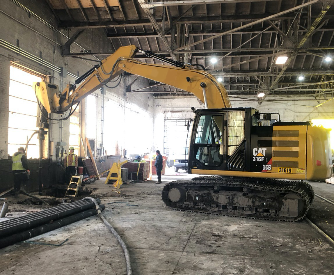
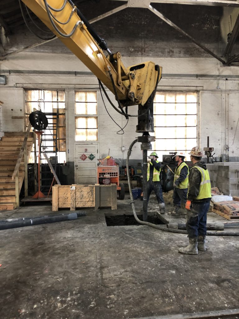
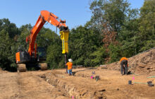
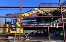
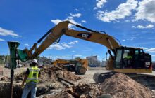
Ductile Iron Piles provided a foundation support solution installed within 20 feet of overhead clearance to support the new crane foundations within the existing facility.
Project Description:
Improvements to the Norfolk Southern Mill Shop included a new 20 ton crane rail system. The 48-ft wide crane rail system was designed to run 180 feet through the interior of the mill shop. Plans required 16 new foundations for crane support; 8 on each side of the crane rail. Column loads included a combination of axial (68 kips), lateral (up to 5 kips) and overturning moments (up to 54 k-ft in one direction). Foundation selection had to consider the limited 20 foot overhead clearance within the existing mill shop.
Geotechnical Details:
Soil conditions consisted of 7 feet of sand fill underlain by soft to stiff silt and clay to a depth of about 40 feetfollowed by medium dense to very dense sand. Groundwater was encountered near 40 feet at the top of the sand.
Project Challenges:
Provide a foundation support solution installed within 20 feet of overhead clearance to support the new crane foundations within the existing facility.
Design and Construction Solution
The geotechnical engineer initially recommended micropiles and augercast piles as typical options for restricted overhead clearance applications. The General Contractor investigated additional cost- effective piling options and approached DuroTerra about a Ductile Iron Pile solution. DuroTerra and engineers at Geopier Foundation Company developed a solution consisting of friction Ductile Iron Piles installed through the upper silt and clay to terminate in the sand to develop capacity to support the crane foundations.
The pile caps were isolated and required a group of three piles to maintain rotational stability. The pile design loads were up to 46 kips (compression) and 2 kips (lateral). Only minor tension loads (< 5 kips) were estimated. A Series 118/9.0 Ductile Iron Pile system (118 mm outer diameter with 9 mm wall thickness) installed with a 220 mm oversized conical cap and continuous grouting was designed to produce an 8-inch diameter grouted pile. A 10-ft long, #6 Grade 75 threadbar was inserted into the pile to resist the minor tension loads and hold the bearing and tension plates.
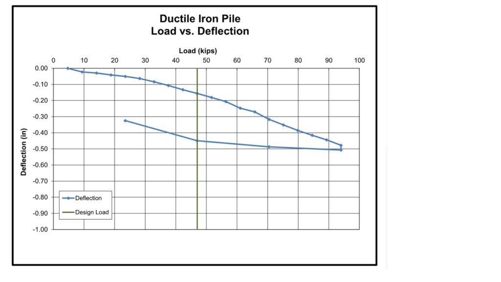
Peterson Contractors, Inc. performed Ductile Iron Pile installations at the site using a mobile CAT 316 excavator with a CAT H120 hydraulic hammer. During installation of the test pile, driving resistance (rate of advancement) substantially increased below depths of 35 feet. The test pile achieved “set” of less than 1 inch of movement in 50 seconds at a depth of 47 feet suggesting an end-bearing condition on the very dense sand. The full-scale load test was performed after 5 days. Test results showed 0.16 inches of deflection at 47 kips (100%) and 0.51 inches at (200%).
Production piles proceeded during the interim between test pile installation and full-scale load testing to help accelerate the schedule. Only 2 of the 3 piles were installed at each location initially to reduce the risk of pile cap geometry changes if the test results were unanticipated. Once the test results verified adequate performance asdesigned, the remainder of the piles in each group were installed. All piles were installed in similar fashion as the load test and achieved dense driving and set in the dense sand. A total of 48 piles were installed to depths of about 45 feet in 3 working days.

